Ceiling Fan With Light Wiring Diagram - How Can I Replace A Ceiling Fan Plus Light With Just A Light Home Improvement Stack Exchange : Every wire connected to a switch are hot wires.
Ceiling Fan With Light Wiring Diagram - How Can I Replace A Ceiling Fan Plus Light With Just A Light Home Improvement Stack Exchange : Every wire connected to a switch are hot wires.. Connect the black wires together. Wiring a ceiling fan & light with speed regulator and light dimmer switch controlled by a common spst switch in this case, we have four wires from the ceiling fan. If you know that the green will be for ground all the time, red for positive, black for negative, blue for remote wire etc. From the switches 3 wire cable runs to the ceiling outlet box. The above ceiling fan wiring diagram depicts the power going into the switch electrical box first and then a switched hot and a neutral go up to the ceiling electrical box on a two conductor cable.
Ceiling fan troubleshooting repair hometips. Wiring diagram for ceiling fan light kit fresh wiring diagram for. It shows the elements of the circuit as streamlined shapes, and also the power and signal connections in between the tools. With this method the fan and light are both controlled by the wall switch. Click on the image to enlarge, and then save it to your computer by right clicking on the image.
Wiring A Ceiling Fan Light Part 2 from www.renovation-headquarters.com The loop terminal on the wall switch is utilised when multiple switches are used to operate the lights in one light circuit. Pick the diagram that is most like the scenario you are in and see if you can wire up your fan! Hunter ceiling fan light kit wiring diagram collection. The source is at the switches and the input of each is spliced to the black source wire with a wire nut. In the circuit, the phase line is connected parallel to the one pole of the two spst switches and the neutral line is connected parallel to the neutral terminal of both fan and. Diagrams for bathroom exhaust fans and timers. This setup allows you to control the light and fan separately. Fan speed would need to be controlled by a pull chain or in some newer fans a wireless remote.
From the switches 3 wire cable runs to the ceiling outlet box.
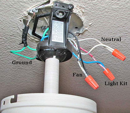
Variety of ceiling fan and light wiring diagram. A single fan and light control using an individual switch is a very commonly used wiring circuit in house, offices, etc. To accomplish this aim, we highlight and examine the four major wires that such fans do possess. Do not modify or damage the antenna wire, as control performance may be reduced. With this method the fan and light are both controlled by the wall switch. Connect the black wires together. Every wire connected to a switch are hot wires. It could be a single switch wiring or double switch wiring. Mark sullivan has been a handyman for. Assortment of hunter ceiling fan and light control wiring diagram. Diagrams for bathroom exhaust fans and timers. Variety of wiring diagram for hunter ceiling fan with light. Lastly, connect the blue wires together, or the blue wire to the black wire for lights.
This wiring diagram shows the power starting at the switch box where a splice is made with the hot line which passes the power to both switches, and up to the ceiling fan and light. The red wire as live to fan, the blue wire as live to the light bulb, the black wire as neutral and green / yellow as ground wire. Moreover, sometimes this wire can come. You can interchange or replace the color of live wire if you have multiple devices connected though the same path or at the same place. Refer to the wiring diagram in figure 3.
Ceiling Fan Switch Wiring Electrical 101 from www.electrical101.com Connect the remaining ceiling fan wires to the circuit wires following the fan manufacturer's wiring diagram. If you know that the green will be for ground all the time, red for positive, black for negative, blue for remote wire etc. It could be a single switch wiring or double switch wiring. Wiring a ceiling fan & light with speed regulator and light dimmer switch controlled by a common spst switch in this case, we have four wires from the ceiling fan. Wiring diagram for ceiling fan light kit fresh wiring diagram for. The black wire on the fan is the supply wire of the fan, the blue one is the light supply line. a ceiling fan wiring diagram for us/ canada. It shows the elements of the circuit as streamlined shapes, and also the power and signal connections in between the tools.
In a typical installation, the white (neutral) fan wire connects to the white (neutral) circuit wire, and the black (hot) fan wire connects to the black (hot) circuit wire.
With these diagrams below it will take the guess work out. Diagrams for bathroom exhaust fans and timers. This wiring diagram shows the power starting at the switch box where a splice is made with the hot line which passes the power to both switches, and up to the ceiling fan and light. This might seem intimidating, but it does not have to be. Wiring diagrams for a ceiling fan and emerson light schematics hampton bay diagram switch with 3 installation bathroom sw90 owner s manual manualzz cf712orb02 sd pull chain rc212 owners bp7415 sr330 controller user troubleshooting repair crofton cf790bs00 parts carroll cf3900ab01 bp7234 the casablanca teardown instructions i always get reviews what. Connect the green wire to your household ground wire (copper/bare wire). Standard hampton bay ceiling fan without a remote has an easy and straightforward ceiling fan wiring diagram. Take a closer look at a ceiling fan wiring diagram. A wiring diagram is a simplified traditional photographic representation of an electrical circuit. Connect the remaining ceiling fan wires to the circuit wires following the fan manufacturer's wiring diagram. Connect the black wire from the ceiling to the black wire from the receiver. Be sure the antenna is positioned securely, so it can not interfere with the ceiling fan motor. The fan and a lighting assembly.
Connect the black wire from the ceiling to the black wire from the receiver. Wiring a ceiling fan and light can seem like a daunting task, but it doesn't have to be. The above ceiling fan wiring diagram depicts the power going into the switch electrical box first and then a switched hot and a neutral go up to the ceiling electrical box on a two conductor cable. Connect the green wire to your household ground wire (copper/bare wire). Wiring diagrams for a ceiling fan and emerson light schematics hampton bay diagram switch with 3 installation bathroom sw90 owner s manual manualzz cf712orb02 sd pull chain rc212 owners bp7415 sr330 controller user troubleshooting repair crofton cf790bs00 parts carroll cf3900ab01 bp7234 the casablanca teardown instructions i always get reviews what.
Wiring Diagram For A Ceiling Fan And Light With The Source At The Ceiling Ceiling Fan Wiring Ceiling Fan With Light Ceiling Fan from i.pinimg.com Wire a ceiling fan, i will show you how to wire two types of ceiling fans. Ceiling fan and light wiring circuit diagram. How to install a ceiling fan dummies wiring double switch for new ceiling fan electrical diy how to install a ceiling fan this old house wiring diagrams for a ceiling fan and light kit do it yourself red wire ceiling fan wiring 7 diagrams for a sm tech. Pick the diagram that is most like the scenario you are in and see if you can wire up your fan! The fan and a lighting assembly. Connect the three white wires from the ceiling, fan, and receiver together. Mark sullivan has been a handyman for. You can interchange or replace the color of live wire if you have multiple devices connected though the same path or at the same place.
Pick the diagram that is most like the scenario you are in and see if you can wire up your fan!
Be sure the antenna is positioned securely, so it can not interfere with the ceiling fan motor. Every wire connected to a switch are hot wires. Fan speed would need to be controlled by a pull chain or in some newer fans a wireless remote. It could be a single switch wiring or double switch wiring. The blue and black wires are twisted together on the fan with the black wire from the house wiring. Connect the white wires (neutral wires) from your fan and ceiling together. A single fan and light control using an individual switch is a very commonly used wiring circuit in house, offices, etc. It shows the components of the circuit as simplified shapes, and the facility and signal friends amongst the devices. The black wire on the fan is the supply wire of the fan, the blue one is the light supply line. Ceiling fan troubleshooting repair hometips. The loop terminal on the wall switch is utilised when multiple switches are used to operate the lights in one light circuit. Wiring diagram for ceiling fan light kit fresh wiring diagram for. Standard hampton bay ceiling fan without a remote has an easy and straightforward ceiling fan wiring diagram.
This article contains a ceiling fan wiring diagram and a light kit ceiling fan with light. This might seem intimidating, but it does not have to be.


0 Comments